


Product Summary:
Features of ML33HP high-precision eddy current displacement sensor: high precision, high resolution, and high temperature stability; External non-contact measurement, no wear; It is particularly suitable for complex working conditions, such as oil stains, high and low temperature environments, etc.
- Product Overview
- Technical Parameters
- Size selection
I. Working Principle of ML33HP High-Precision Eddy Current Displacement Sensor
The working principle of the eddy current sensor system is the eddy current effect, which belongs to an inductive measurement principle. The eddy current effect originates from the energy of the oscillation circuit. However, eddy currents can only be formed within conductive materials. Introducing an alternating current into the coil inside the sensor probe can create a magnetic field around the probe coil. If a conductor is placed in this magnetic field, according to Faraday's law of electromagnetic induction, eddy currents will be excited within the conductor. According to Lenz's Law, the magnetic field direction of the eddy current is exactly opposite to that of the coil, and this will change the impedance value of the coil inside the probe. The variation of this impedance value is directly related to the distance between the coil and the object being measured. After the sensor probe is connected to the controller, the controller can obtain the change in voltage value from the sensor probe and calculate the corresponding distance value based on this. The eddy current measurement principle can measure all conductive materials.
Because eddy currents can penetrate insulators, even metal materials with insulators on their surfaces can be used as the objects to be measured by eddy current sensors. The unique coil winding design not only makes the sensor compact in shape but also meets the requirements for its operation in high-temperature measurement environments.
II. Application Fields of ML33HP High-precision Eddy Current Displacement Sensor
By measuring the relative position between the metal object to be measured and the probe end, the eddy current displacement sensor senses and processes it into the corresponding electrical signal output. The sensor can work reliably for a long time, has high sensitivity, strong anti-interference ability, non-contact measurement, fast response speed, and is not affected by media such as oil and water. It is widely used in the long-term real-time monitoring of parameters such as shaft displacement, shaft vibration, and shaft speed of large rotating machinery And it has been extended to application fields such as satellite launch, material identification, weighing measurement, metal plate thickness measurement, and material deformation.
III. Features of ML33HP High-Precision Eddy Current Displacement Sensor
★ High precision, high resolution, and high temperature stability
★ External non-contact measurement, no wear
It is particularly suitable for complex working conditions, such as oil stains, high and low temperature environments, etc
IV. Technical Parameters of ML33HP High-Precision Eddy Current Displacement Sensor
Measuring range | 1mm | 2mm | 4mm | 5mm | |
Probe diameter | Φ8mm | Φ8mm | Φ11mm | Φ17mm | |
Linear error(%FS) | ≤±0.1%FS | ≤±0.1%FS | ≤±0.1%FS | ≤±0.15%FS | |
Repeatability | 0.5µm | 0.5µm | 1µm | 1µm | |
Resolution | 1µm | ||||
Frequency response | 0~10KHz | 0~8KHz | |||
Output signal | 4-20mA,0-5V,0-10V,RS485 | ||||
Supply voltage | +12-24VDC | ||||
Working current | Voltage type < 45mA, current type < 25mA, RS485 type < 40mA | ||||
Operating temperature | Probe: -20℃ to +60℃, preamplifier: -20℃ to +80℃ | ||||
Protection grade | Probe: IP67, preamplifier: IP65 | ||||
· Probe cable | Default: 2m, customizable | ||||
Power cable | Default: 2m, customizable | ||||
V. Wiring Definition: (The specific wiring method is subject to the actual product.)
Cable color | Current type | Voltage type | RS485 |
Brown | Power positive +24VDC | Power positive +12~24VDC | Power positive +12~24VDC |
Black | None | Power negative 0V | Power negative 0V |
Blue | Current output OUT | Output Positive OUT+ | RS485 A+ |
White | None | Output negative OUT- | RS485 B- |
Shielded wire | GND | GND | GND |
VI. Selection Guidance
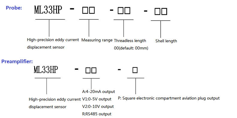
VII. Installation Dimensions
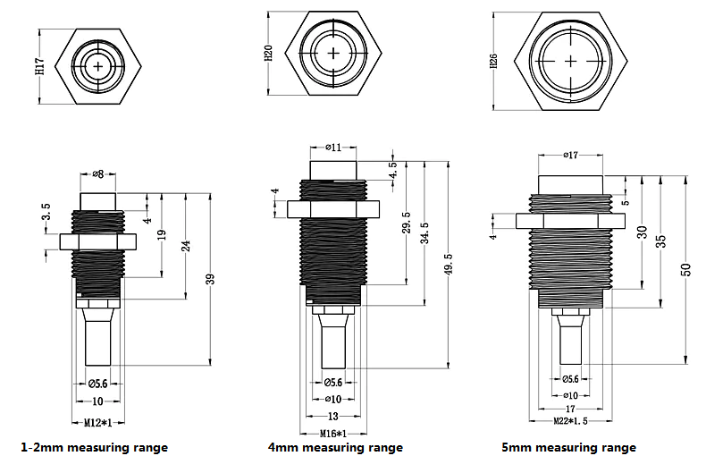
1. Probe
A probe is usually composed of a coil, a head, a housing, a high-frequency cable and a high-frequency connector.
During the manufacturing process, the probe head body is generally made of high-temperature resistant PPS engineering plastic, and the coil is sealed inside through "secondary injection molding". Enable the probe to work reliably in harsh environments. Since the diameter of the head body coil determines the linear range of the sensor system, we usually classify and characterize each type of probe by the external diameter of the head body. Generally, the linear range of the sensor system is approximately 1/2 to 1/4 times the diameter of the probe head.
The probe housing is used to connect and fix the probe head and serves as the clamping structure when installing the probe. The shell is generally made of 304 stainless steel by process, with standard threads engraved on it and equipped with lock nuts. In order to adapt to different applications and installation scenarios, the probe housing comes in various forms, with different threads and size specifications.
Probe external dimension drawing
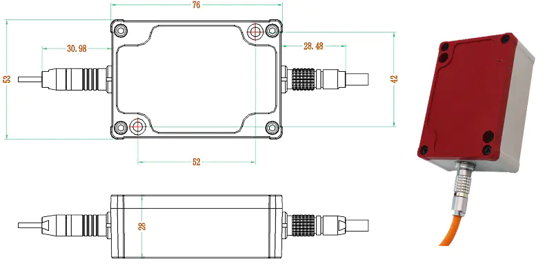
2. Preamplifier
The preamplifier is the signal processing center of the entire sensor system. On the one hand, the preamplifier provides high-frequency alternating current excitation to the probe coil to make the probe work; On the other hand, the preamplifier senses the gap changes between the probe head body and the metal conductor in front of the head body through a special circuit. After processing by the preamplifier, a voltage or current output signal that varies linearly with the gap is generated.
Preamplifier external dimensions diagram