


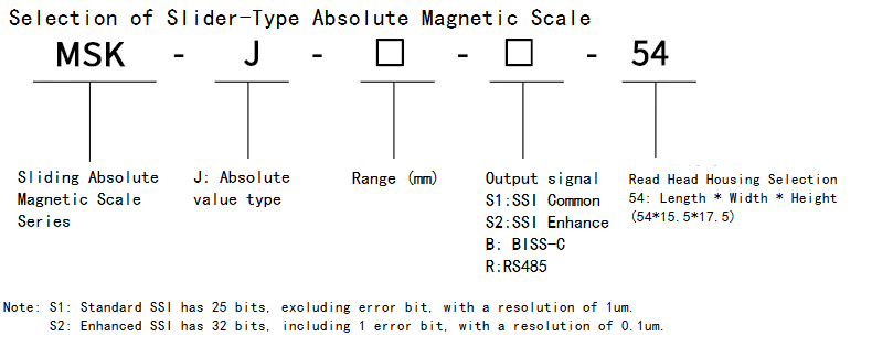
Product Summary:
The maximum measurement range of the MSK slider type absolute value magnetic grating ruler can reach 16.384 meters, offering a wider range of selectable measurement options. The absolute value magnetic grating ruler is a high-precision sensor used for linear or rotational position measurement. Its core working component is divided into two main parts: the "magnetic grating ruler" with uniformly recorded magnetic scales on its body and the "reading head" equipped with magnetic sensitive elements inside. When moving above the ruler, the absolute position information of the magnetic signal can be read. Unlike incremental rulers, there is no need to first return to zero to find the reference point. Even if the power is cut off in the middle, the position information will not be lost. After the power is restored, the position remains accurate.
- Product Overview
- Technical Parameters
- Size selection
I. Overview of MSK Slider Type Absolute Value Magnetic Grating Scale
The maximum measurement range of the MSK slider type absolute value magnetic grating ruler can reach 16.384 meters, offering a wider range of selectable measurement options. The absolute value magnetic grating ruler is a high-precision sensor used for linear or rotational position measurement. Its core working component is divided into two main parts: the "magnetic grating ruler" with uniformly recorded magnetic scales on its body and the "reading head" equipped with magnetic sensitive elements inside. When moving above the ruler, the absolute position information of the magnetic signal can be read. Unlike incremental rulers, there is no need to first return to zero to find the reference point. Even if the power is cut off in the middle, the position information will not be lost. After the power is restored, the position remains accurate.
II. Characteristics and Applications of MSK Slider Type Absolute Value Magnetic Grating Scale
It has strong anti-interference ability and is not sensitive to industrial environments such as oil stains, dust and vibration, with high reliability.
No need to return to zero, saving time and preventing production problems caused by unexpected power outages.
It is easy to maintain, usually does not require a battery to keep memory, and has a sturdy structure.
It is widely applied in scenarios that require high reliability and absolute position memory, such as CNC machine tools, precision measuring equipment, automated production lines, medical equipment, robots, etc.
MSK Slider type absolute value magnetic grating scale
Dual-channel absolute value magnetic grating scale encoder
2. The period coding length is 16,384mm.
3. The speed can reach 5m/s.
4. Support SSI, BISS-C, RS485 (MODBUS-RTU)
III. MSK Slider Absolute Magnetic Scale Technical Parameters:
Resolution | 0.1μm |
Magnetic pole width | 2+2mm |
Range of measurement | 0-16.3m(optional) |
Repetition accuracy | <2µm |
Supply Voltage | DC5V |
Current consumption | 155mA(Max) |
Magnetic stripe precision | ±20um |
Location Data Interface | RS485(MODBUS-RTU),SSI,BISS-C |
Parameter Configuration Interface | RS485 |
Protection rating | IP67 |
SSI clock frequency input | ≤750KHz(Depends on the cable length) |
Maximum speed | 5m/s |
Seismic resistance | 300m/s2 |
Cable length | Default 2 meters (maximum 10 meters) |
Installation spacing between magnetic stripe and magnetic head | 0.4(mm)±0.1mm |
IV. MSK Slider Absolute Magnetic Scale Wiring Method:
Output signal | Red | Black | Blue | White | Yellow | Green | Shielded Wire |
RS485 | 5VDC | 0V | A | B | NC | NC | GND |
SSI | 5VDC | 0V | D+ | D- | C+ | C- | GND |
BISS | 5VDC | 0V | MA+ | MA- | SLO+ | SLO- | GND |
SSI Technical Requirements
Frequency | Bit | Code | Resolution | Remark |
100khz- 1Mhz | 25 bit | Gray code | 1um | Factory default |
100khz- 1Mhz | 32 bit | Optional | 0.1um | Configurable |
SSI Timing parameters
SSI timing parameters | Symbol | Minimum | Typical value | Maximum value |
Clock frequency | tcl | 10us | 5us | 1us |
Clock frequency | tcl | 100Khz | 200Khz | 1Mhz |
Transmission timeout | tm |
| 10us |
|
Pause time | tp | 64us | 128us |
|
SSI Data Format
25 Bit
Bit | b24-b0 |
Length | 25 bits |
Data | Position unit 1um |
Code | Gray code |
32 Bit
Bit | b31-b1 | B0 |
Length | 31 bits | 1 bit |
Data | Position unit 0.1um | Error position |
Code | Gray code |
|
BISS-C Technical Requirements
Frequency | Data bits | Code | Resolution | Remark |
100khz- 1Mhz | 30 bits | Binary | 0.1um | Factory default |
BISS-C Timing Parameters
Parameter | Symbol | Minimum | Typical value | Maximum value |
Clock frequency | tMA | 1us |
| 10us |
Clock frequency | f | 100Khz |
| 1Mhz |
ACK Length | tACK |
| 1bits |
|
Transmission timeout | tM |
| 10us |
|
Pause time | tP |
| 64us |
|
BISS-C Data Format
Bit | b38-b8 | b7 | b6 | b5:b0 |
Length | 30bits | 1bit | 1bit | 6bits |
Data | Position Unit 0.1um | Error position | Warning Bit | CRC |
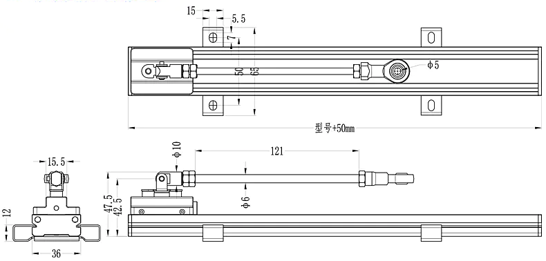
V. Installation Dimensions and Selection Guidance
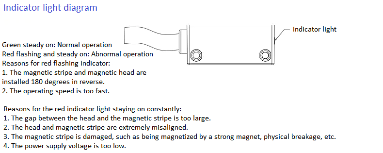
VI. Installation Steps and Precautions:
The magnetic grating ruler is made of magnetic materials. When the magnetic grating ruler is disturbed by an external magnetic field, the external magnetic field will change its functional properties. When the magnetic field is ≥1mT, it will reduce the accuracy of the system. When it is ≥20mT, it will damage the magnetization intensity of the magnetic scale. The function of the system may no longer be guaranteed. Direct contact with magnetic fixtures or other permanent magnets must be avoided.
2. The installation of the magnetic grating ruler must use a magnetizer (guide mounting component).
3. The magnetic grating ruler with absolute value is of double code tracks, and the magnetic resistance of the reading head corresponds to the incremental code. Pay attention to the installation direction.
4. After the reader is assembled with the magnetic scale, pay attention to issues such as misalignment, uneven clearance, and tilting.
5. The fixed brackets for the reading head and the magnetic scale should be consistent.
6. If the on-site environment contains a lot of dust or foreign objects, it is recommended to use a shielding cover for protection.